1. Proposal of the Problem
(1) Introduction to Common Cycle Instructions for Thread Turning Thread turning is a machining process used to create a specific spiral groove on a lathe by maintaining a precise relationship between the feed motion and the spindle rotation. The shape of the thread is primarily determined by the geometry and positioning of the cutting tool, while the pitch is controlled by the feed rate of the tool. In modern Fanuc and Guangzhou CNC systems, three main commands are typically used for thread cutting: G32, G92, and G76. G32 is a straight-cut method, G92 is a fixed-cycle straight-through cutting command, and G76 is a compound cycle with diagonal feeding. The straight-through method is simple to program but involves both cutting edges being subjected to force simultaneously, which can lead to tool wear and chipping. This makes it more suitable for threads with small pitches (P ≤ 2 mm). On the other hand, the oblique feeding method ensures that only one side of the tool cuts at a time, reducing the risk of chipping. However, when dealing with large pitch or special thread profiles, vibration can occur due to increased cutting forces and deeper cuts.
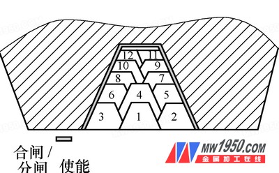
(2) Comparison of Common Cycle Command Machining Paths for Thread Turning The path of the straight-cut thread command G92 is illustrated in Figure 1, while the oblique-cut command G76 is shown in Figure 2. These two methods are commonly used in CNC lathes, but they may not be ideal for complex or high-pitch threads. Another alternative is the left-and-right cutting method, which is particularly useful for roughing large pitch or multi-start threads. This technique allows for reduced cutting forces per pass and better tool life. As shown in Figure 3, the cutting sequence follows 1→2→3→4→5→6→7→8→9→10→11→12, with each layer’s back-off amount adjusted accordingly. After roughing, finishing operations are required to ensure proper tooth profile and surface quality.

Figure 1: G92 Command Cutting Path

Figure 2: G76 Command Cutting Path

Figure 3: Left and Right Infeed Sequence
Given the limitations of standard thread cutting commands, macro programs offer greater flexibility through variable settings, conditional logic, and advanced control functions. This makes them ideal for handling complex thread profiles such as shaped, arc-shaped, or variable-pitch threads, where precise control over tool path, depth, and dimensions is essential.
2. Application Research Case
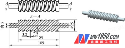
(1) Special-Shaped Thread Process and Cutting Amount Selection As shown in Figure 4, the workpiece features a special-shaped thread with a pitch of 10 mm, a single-sided depth of 2.5 mm, a flank angle of 30°, and an alveolar bottom width of 3.2 mm. The axial length of the thread is 89 mm, with 20 mm of φ10 mm sections on either end. The material is 45 steel, and the thread is machined using a macro program. This approach enables accurate control over the complex geometry, ensuring consistent thread form and minimizing tool wear during deep cutting operations.

Figure 4: Main Dimensions of the Profiled Thread and 3D Model
Smart Mirror,Ceramic Glass,Smart Silver Mirror,Smart Bathroom Mirror
SHANDONG TOP LEADER GLASS CO.,LTD , https://www.topleaderglass.com