Foreword
This standard was drafted in accordance with the rules given in GB/T 1.1-2009.
This standard was proposed and managed by the Guangdong Provincial Bureau of Quality and Technical Supervision.
This standard is drafted by: Shenzhen Chuangyi Technology Development Co., Ltd., Shenzhen Standard Technology Research Institute, Shenzhen Haowei Photovoltaic Lighting Co., Ltd., Shenzhen Metrology and Quality Inspection Institute.
The main drafters of this standard: Yang Lan, Li Huan, Huang Weizhong, Ni Yizhou, Li Juhuan, Ren Jiwei, Jiang Ximeng, Huang Manxue, Wen Lifeng, Cui Mingxian, Li Zhijian, Li Quanxiang.
1 Scope
This specification stipulates the classification, requirements, design documents, signs, specifications, packaging, transportation and storage of solar garden lights powered by solar photovoltaic modules.
This specification applies to the design of solar garden lights in Guangdong Province.
2 Normative references
The following documents are indispensable for the application of this document. For dated references, only the dated version applies to this document. For undated references, the latest version (including all amendments) applies to this document.
GB/T 191 packaging, storage and transportation logo
GB/T 6995 wire and cable identification marking method (all parts)
GB 7000.1 Luminaires Part 1: General Requirements and Experiments
GB/T 9969 Instruction Manual for Industrial Products
GB/T 22473 lead-acid battery for energy storage
GB/T 24909 LED lamps for decorative lighting
HJ/T 230 Environmental Labeling Products Technical Requirements Energy Saving Lamps
JB/T 11139 Lithium Manganese Battery Module General Requirements
General requirements of JB/T 11140 lithium iron phosphate battery module
SJ/T 207.2 Design Document Management System Part 2: Format of Design Documents
SJ/T 207.4 Design Document Management System Part 4: Design Document Numbering
SJ/T 207.5 Design Document Management System Part 5: Design Document Changes
SJ/T 207.7 Design Document Management System Part 7: Preparation of electrical diagrams
3 Terms and Definitions
The following terms and definitions apply to this document.
3.1
Garden lights garden lights
Installed in the courtyard, community and other areas, with lighting and decorative lighting, the general load power is less than 20W.
3.2
Solar garden lights solar garden lights
A garden light that uses solar photovoltaic power generation as a power source.
3.3
Support frame
Structure system for supporting solar garden lights.
3.4
Light source light source
Components that can sustain their own light in solar garden lights.
3.5
Energy storage device
A device in a solar garden light that stores electrical energy and provides power to the light source, typically a battery.
3.6
Controller controller
An automatic control and protection device for charge and discharge of an energy storage device.
Category 4
Divided by solar cell type:
― Crystal silicon solar cell type;
- Thin film solar cell type.
5 design requirements
5.1 Structural Design Requirements
5.1.1 General
The structure design should select standard parts, and the height of solar garden lights should not exceed 4m.
5.1.2 Strength Design
The overall structure should have sufficient strength and stiffness to meet the wind load requirements of the place of use.
5.1.3 Replaceable Parts
In the structural design, there should be enough space to replace the replaceable parts and ensure the safety during the replacement process.
5.1.4 Cabling
The trough should have no defects such as sharp edges, burrs, burrs, etc. that may cause damage to the cable.
5.2 Material Requirements for Supports (Frames)
Metals should be used, or other materials that have been designed to meet the requirements of 5.1.2.
5.3 anti-rust, anti-corrosion requirements
The rust-proof and anti-corrosion requirements of the lamps and lanterns shall comply with the provisions in GB 7000.1.
5.4 Degree of protection requirements
The degree of protection of the connection of the various parts of the lamp shall not be lower than that of the P54.
5.5 light source requirements
5.5.1 General
Should choose high light efficiency, low attenuation, long life LED lights or energy-saving lamps.
5.5.2 LED lights
The light parameters should comply with the relevant provisions of GB/T 24909.
5.5.3 Energy Saving Lamp
The performance of the energy-saving lamp light source refers to the relevant regulations in HJ/T 230.
5.6 PV Module Design Requirements
5.6.1 Appearance Requirements
Should meet:
a) The front surface is clean and free from defects such as cracks and cracks;
b) No scratches, damage, etc. on the back surface;
c) Single solar cells are arranged neatly, well sealed, free of defects such as breakage, cracks, etc.;
d) The interconnections and grid lines are arranged neatly without defects such as soldering and fracture;
e) no continuous bubbles or delamination in the encapsulating layer;
f) The lead end seals well and the polarity mark is accurate and obvious.
5.6.2 Electrical Performance Requirements
The operating voltage of the photovoltaic module should meet the requirements of the battery charging voltage. Photovoltaic module system configuration calculations are shown in Appendix A.
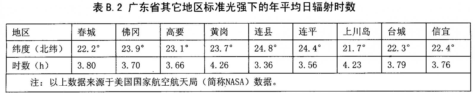
The difference between the measured value and the nominal value of the PV module power shall be within ±10% of the nominal value. The total power of PV modules shall be determined according to the lighting resources used in the environment, the power consumption of the load, and the energy consumed by the designed number of rainy days. The annual average daily radiation time under standard light intensity in parts of Guangdong Province is referred to Appendix B.
5.6.3 Security Requirements
Should meet:
a) After the solar cell is encapsulated, no external surface of the solar cell will damage the protruding structure of the human body;
b) No exposed live body except for solder joints after solar cell packaging;
c) The photovoltaic module does not cause heat burst due to heat generation;
d) For components with an area of ​​less than 0.1m2, the insulation resistance is not less than 400mQ; for components with an area of ​​more than 0.1m2, the insulation resistance multiplied by the area of ​​the component should not be less than 400mQ.m2.
5.7 Controller Requirements
5.7.1 The controller should have the following protection features:
a) circuit protection capable of withstanding a short-circuit of the load, internal short-circuiting of the charge-discharge controller;
b) Circuit protection capable of withstanding reverse polarity of loads, photovoltaic modules or batteries;
c) Ability to withstand breakdown protection caused by lightning strikes in multi-zones;
d) Protection against battery reverse discharge through PV modules.
5.7.2 For a system with a solar array power (peak) greater than 20 W, the controller itself should have the function of full battery disconnect and under voltage disconnect.
5.7.3 The controller has the function of full input to disconnect and resume the connection.
5.7.4 The controller shall have a temperature compensation function in case of large changes in the operating environment temperature.
5.7.5 When the battery voltage drops to the overdischarge point ((1.80±0.05)V/only) the controller should be able to automatically cut off the load; when the battery voltage rises back to the charge recovery point ((2.2-2.25)V/only), the control The device should be able to automatically or manually restore power to the load.
5.7.6 The system shall provide the user with indication of the state of charge of the battery, such as full charge, under voltage and load cut-off. Indicators can be light emitting diodes (LEDs), analog or digital meters, or beep alerts. These devices must have obvious instructions or signs.
5.7.7 The maximum no-load loss of the controller must not exceed 1% of its rated charging current.
5.7.8 Charge or discharge The voltage drop across the controller must not exceed 5% of the system's rated voltage.
5.7.9 When the battery is removed from the circuit, the controller must be able to withstand an impulse of 1.25 times the nominal open circuit voltage of the PV module within 1 hour.
5.7.10 The controller must be capable of withstanding 1 h higher than 1.25 times the nominal short circuit current of the PV module.
5.7.11 The controller can have time-controlled and light-controlled functions according to design requirements.
5.8 Energy Storage Device Requirements
5.8.1 Performance Requirements
When a lead-acid battery is used, its performance shall comply with the relevant provisions in GB 22473. When manganese acid buried batteries are used, their performance and electromagnetic compatibility requirements shall comply with the relevant provisions of JB/T 11139. When using a ferrous phosphate tantalum battery, its performance and electromagnetic compatibility requirements shall comply with the relevant provisions of JB/T 11140. Select other types of energy storage devices whose performance should meet or exceed the relevant requirements in the above three standards.
5.8.2 Combination Method
The battery pack can consist of multiple batteries connected in series or in parallel.
5.8.3 Connection method
The battery shall be provided with poles that are easily connected by bolts. The poles shall be rust-proofed and marked positively and negatively.
5.8.4 Capacity Requirements
Battery capacity configuration should meet the design requirements.
5.9 Cable Selection Requirements
5.9.1 internal cable cross-sectional area requirements
When the power of the module is less than 10W, the cross-sectional area of ​​the cable shall not be less than 0.5mm2; when the power of the module is greater than or equal to 10W, the cross-sectional area of ​​the cable shall not be less than 1.5mm.
5.9.2 Cable line voltage drop
Should meet:
a) When the PV module charges the battery with the rated current through the controller, the line voltage drop should not exceed 3%;
b) When the battery discharges the lighting component through the controller at the rated current, the line voltage drop between the output terminal of the battery and the battery connection terminal of the controller shall not exceed 1% of the rated voltage of the battery; the output end of the controller and the input end of the lighting component The pressure drop should not exceed 3% of the battery's rated voltage.
5.9.3 Cable Identification Requirements
6 design documents
6.1 file content
Should meet:
a) The design documents fully describe the design information of the software and hardware components, types, structures, interfaces, and principles of solar garden lights and the technical data and instructions necessary for manufacturing, acceptance, use, and maintenance;
b) The design documents are accurate and clear, and the documents are coordinated. The preparation of design documents meets relevant standards;
c) Record the same design file number and change mark in the same product design technology file with different media, and the technical content of the record is the same.
6.2 File Numbers and Formats
The design documents shall be given a number. The provisions of the numbering shall refer to the relevant provisions in SJ/T 207.4; the format of the design documents shall be referred to the relevant provisions in SJ/T 207.2.
6.3 file changes
Should meet:
a) There is a basis for changing the design documents, taking into account the advanced nature of the technology, the feasibility of production and the rationality of the economy;
b) change the design document according to the approved design document change notice;
c) The design document is complete, correct, unified, and coordinated so as to ensure smooth production;
d) The change of the design document is consistent with that of the base map, the copying plan and the product; the consistency of the reference design document, the work design document and the product is maintained;
e) changes to the design document reflect the change process and the post-change status of the design document;
f) When design documents are changed, their associated design files are changed at the same time;
9) The revised design documents are kept clean and tidy;
h) The method of changing the design document refers to the relevant provisions in SJ/T 207.5.
6.4 Electrical diagram
Should meet:
a) Electrical schematics follow the guidelines for the preparation of product design documents;
b) Descriptions, diagrams and diagrams are clear;
c) The text is concise and easy to understand;
d) Convenient product development and updating;
e) the use of computer-aided design to meet the requirements of the relevant standards;
f) The rest meets the relevant requirements in SJ/T 207.7.
7 signs, instructions, packaging, transportation and storage
7.1 Logo
The device should have the following clear and firm signs:
a) product name, model, trademark;
b) specifications, models of supporting photovoltaic components, controllers, energy storage devices, light sources, etc.;
c) Manufacturer, origin, date of manufacture and serial number, and execution standard number.
7.2 Instructions
Each product should be accompanied by a product instruction manual, the content of which shall comply with the provisions of GB/T 9969. Instructions for use in addition to those in 7.1
In addition to all projects, the following should also be included:
a) product use precautions;
b) installation instructions;
c) maintenance.
7.3 Packaging
Each part of the device should be separately packaged and should meet:
a) The packing box meets the requirements of moisture proof, shockproof, etc.;
b) The identification outside the box complies with the provisions of GB/T 191;
c) The packing box contains the parts list, instruction manual, product certification, and other documents.
7.4 Transportation
Should meet:
a) Requirements for loading, unloading and transport, and protective conditions during transportation;
b) Prevent rain, snow and strong shocks;
c) The device will be described when there are special transportation needs.
7.5 Storage
The device should be stored in a well ventilated room with a relative humidity of no more than 80% and no corrosive gas in the air.
Appendix A
(Informative Appendix)
System configuration calculation
A.1 Battery Capacity Calculation

A.2 PV array design calculation
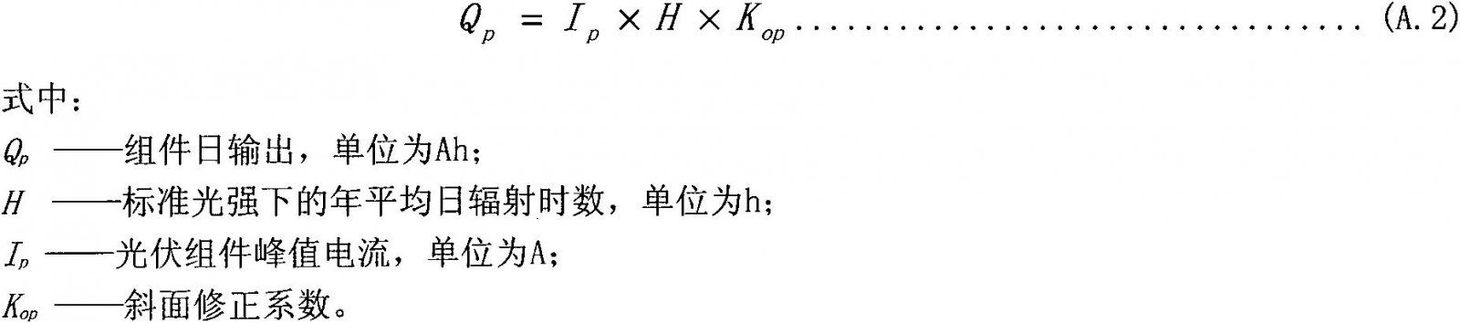
A.2.1 Daily output of photovoltaic modules
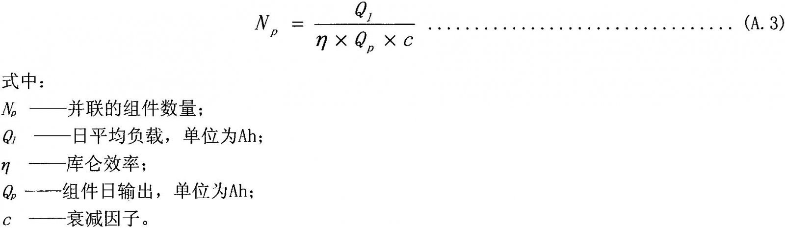
A.2.2 Number of Components Connected in Parallel
A.2.3 Number of Components in Series
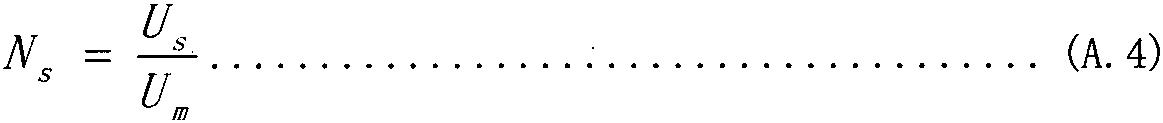
In the formula:
NS - the number of concatenated components;
Us-system voltage in units of V;
Um - The component voltage in units of V.
A.3 Checking Accumulator and Photovoltaic Array Design
A.3.1 Checking the Average Daily Discharge Depth of the Battery
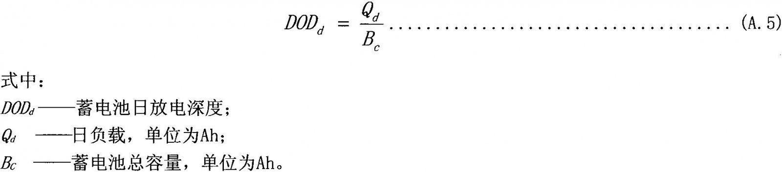
An example of a photovoltaic system using a 4000 Ah deep-cycle battery with a daily load of 500 Ah, the average daily DOD check is calculated as follows:
500Ah/4000Ah=0.125<0.8
Therefore, the battery in the system will not be over-discharged.
A.3.2 Checking the maximum charging rate of the PV array to the battery pack
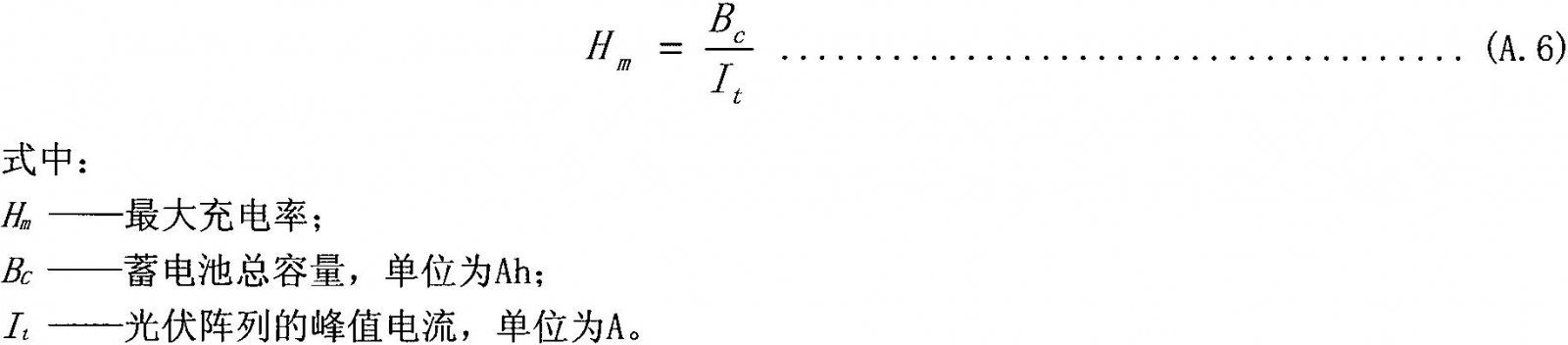
An example of a photovoltaic power supply system using 75W photovoltaic modules 25 parallel 2 series, 24V working voltage, the use of 4000Ah battery, the maximum charging rate of the check calculation is as follows:
Maximum charging rate = 4000Ah/(25X4.4) (75W component peak current) = 36.4h
The calculated value is compared with the maximum charging rate of the battery of the design and model provided by the battery manufacturer. If the calculated value is small, the design is safe. The charging rate of the storage battery by the photovoltaic array will not harm the battery. If the calculated value is large, The design is unqualified and needs to be redesigned.
Appendix B
(Informative Appendix)
Annual average daily radiation hours under standard light intensity in parts of Guangdong Province

At present, with the increase of global population and the development of industrialization, more and more solid wastes such as municipal solid waste and industrial solid waste are produced. How to effectively dispose of garbage is a problem that people all over the world are facing. On the basis of our previous experience and continuous research and innovation, our company finally developed MSW Gasification Power Plant. According to different treatment methods, it can be divided into Msw Gasification, Municipal Solid Waste Power Plant and Rdf Power Plant (garbage into derivative particles RDF) and other waste energy projects.

Msw Incineration,Msw Gasification Power Plant,Msw Gasification Power Generation Plant,Rice Husk Gasification Power Plant
Henan Dianyan New EnergyTechnology Co. Ltd , https://www.cngasifier.com