The double-turret CNC lathe adopts multi-blade simultaneous cutting, which can shorten the working hours and improve the production efficiency, and is applied in mass production. The geometric data and process data of CNC machining are the original basis for the operation of NC machine tools and are determined by the drawings of the parts to be machined. With the automatic programming system for NC programming, the process route, the path of the tool, the cutting parameters and the auxiliary functions (tool change, shifting, coolant opening and closing, etc.) must be obtained in a CAPP manner.
For CNC machining of workpieces with large deviations in blank size, if the conventional programming method is used, it must be programmed according to the maximum blank size. If programmed at the maximum size, one is less efficient, and then it will cause an empty cut in some cases, and may cause overcutting in another case. The consequences of overcutting can affect the durability of the tool, and the damage to the tool affects the accuracy of the machine. Therefore, the numerical control machining of the workpiece with large blank deviation is preferably based on the specific conditions of each workpiece to determine the cutting parameters (such as cutting allowance, number of passes, etc.) for machining the workpiece. The programming system uses the tool monitoring function of the numerical control system to measure the machining allowance distribution of some key points (called measuring points) on the workpiece online, and determines the measuring points (one or more) passed by the working step in the machining process planning. ), thereby obtaining the cutting parameters of the present step. In this paper, we take the "double tool holder CNC lathe graphic automatic programming system" developed by Maanshan Iron and Steel Co., Ltd. as an example to study the CAPP technology of the double tool holder NC programming system. The automatic programming system uses Microstation as a graphics platform to realize CAD/CAPP/NCP system integration.
2 Features of automatic programming CAPP for double tool holder CNC lathe
The double-turret CNC lathe is an efficient CNC machine tool. Due to the simultaneous cutting with double knives, it can effectively shorten the processing time of a single piece and significantly improve the productivity. The degree of productivity improvement depends on the length of the processing time of the left and right tool holders, which means that the double knives should process different surfaces of the workpiece as much as possible. This paper takes the VF120-RW double-turret vertical CNC lathe produced by Diedesheim Machine Tool Co., Germany (the machine is equipped with two sets of SINUMERIK-810T numerical control system) to process the train wheels as an example. The numerical control system of the machine adopts the master-slave control mode. The left tool holder numerical control system is the main system (the machine tool spindle speed is controlled by the left CNC system), the right tool holder numerical control system is the slave system, and the left and right two numerical control systems are M21. The instructions coordinate the actions of the two tool holders and pass the data in R parameters. According to statistics, the processing efficiency can be increased by more than 30% compared with the single-knife CNC lathe.
The machining process planning of the double-turret CNC lathe automatic programming is different from the CAPP process of the automatic programming of the ordinary single-turret CNC lathe. Since the cutting parameters of the machining are unknown when the CAPP is performed, the cutting parameters actually used are measured by the machining process. When performing CAPP, it is necessary to specify the information of the measurement point (one measurement point or multiple measurement points) through which the machining path is traversed. The complexity of the CAPP processing process for double-turret CNC lathes is also reflected in the need to ensure adequate monitoring of the user's planning process to ensure that the geometrical interference and process interference of the process system during processing is not caused. The process planning CAPP uses the M21 command of the numerical control system (the left and right tool holder motion coordination instructions) to carry out the feasibility test of the user's planning to ensure that the left and right tool holders can work correctly under any circumstances during processing without interference. A phenomenon occurs. The system design provides great convenience for the user's CAPP. The planning of the left and right tool post steps can be carried out in turn, or the Other side can be planned after completion.
3 Geometric information of parts and extraction of process information
Process Planning CAPP is a step of planning a process of part processing by human-computer interaction. The step is the basic unit of CAPP data access in the process planning, and the step is identified by the step ID; the plan is organized by the doubly linked list. Data, convenient data storage and modification operations, to ensure that the process planning CAPP is flexible enough (planning process and process parameters can be modified). Each step data consists of two parts: tool movement track data and cutting process data. Since the amount of data recorded in the step is large, the structure is used to record the information to coordinate the internal connection of the data, and at the same time facilitate the operation of the data.
The system makes full use of the GUI technology of the Microstation system to perform human-computer interaction with dialog boxes and Motif-compliant controls. The system has a friendly man-machine interface and is easy to operate. The user interacts with the mouse and the keyboard, and the geometric data of the step is obtained by the mouse in the CAPP graphic file to obtain the contour of the part; the process data of the step is input by the combination of the mouse and the keyboard.
The process planning CAPP takes the graphic file of the measurement process planning and the R point parameter file of the measuring point as input, and the tool list is used as the processing tool loading basis; the processing planning graphic file is output, and the processing process plans the CAPP data file.
The general work step planning consists of five parts, which are: cutting section, cutting section, cutting section, trial section and step ID placement. The cutting section of the machining contour is generally composed of a plurality of geometric pixels (straight lines or arcs), and these pixels are sequentially selected in the order of cutting when performing CAPP. The order of the step planning is: the planning of the cutting section, the planning of the cutting section, the planning of the cutting section, the planning of the trial section (optional) and the placement of the step ID. The step is identified by the step ID.
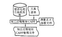
Figure 1 Process Planning CAPP Module Structure
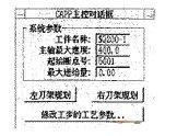
Figure 2 Process Planning CAPP Master Dialog
In the process of planning the CAPP module design (Fig. 1, Fig. 2), in order to adapt to the processing of different types of workpieces and improve the flexibility of CNC machining, a variety of tool cutting modes were designed for selection.
(1) The normal to the workpiece first selects the pixel at the point of entry, and then selects the starting point of the segment. During machining, the tool cuts from the starting point of the planned cutting segment along the normal direction of the machining surface. This method is mainly used in the case where the starting position of the cut-in segment is known.
(2) Normal direction Select the end point of the cut-in segment from the workpiece first, and then determine the position of the starting point of the cut-in segment. This method is mainly used in the case where the end point of the cut-in section is known. Cutting along the normal direction of the machined surface during machining.
(3) Tangential to the workpiece First select the pixel where the cutting point is located, and then select the starting point of the cutting segment. When machining, the tool cuts from the starting point of the planned cutting segment along the tangential direction of the processing surface. This method is mainly used in the case where the starting position of the cut-in segment is known. Cut in the tangential direction of the machined surface during processing.
(4) Tangentially Select the end point of the cut-in segment from the workpiece first, and then determine the position of the starting point of the cut-in segment. This method is mainly used in the case where the end point of the cut-in section is known. Cut in the tangential direction of the machined surface during processing.
(5) Obliquely select the end point of the cut-in segment from the workpiece first, and then select the position to cut into the starting point of the segment. This method is mainly used in the case where the starting and ending positions of the cutting section are known. When machining, cut along the starting point to the end point of the planned cutting section.
In order to meet the numerical control machining of workpieces with low precision of blank manufacturing (for example, large machining allowance, large eccentricity, large curvature or uneven margin, etc.), machining according to conventional methods will damage the tool and may not be processed. In order to accommodate the processing of this type of blank, several special types of processing methods have been defined:
(1) Changing the feed amount When the cutter enters the cut-in section, the feed rate is gradually increased. This method is mainly used for the processing of a large part of the blank eccentricity.
(2) Work step cross cutting After the current step has finished a certain knife, it will jump to the next step for cutting, and after completing the processing of the next step, continue to complete the unfinished step of the current step. The method is mainly used for processing where the curvature of the workpiece contour is large and the machining allowance is uneven.
(3) When the multi-knife cutting difference allows multiple passes, the tool cut-in point and the cut-out point position are variable. This method is mainly used for processing machining where the margin is particularly large, so as to prevent the tool from being damaged by the overcut phenomenon at the point of entry or cut-out.
(4) Interrupting the entry point After the machining process is interrupted, the tool cuts into the workpiece along the additionally set infeed path. This method is mainly used to prevent the interference of the tool and the workpiece that may occur when cutting is continued after the interruption.
For the convenience of operation, on the one hand, a complete online help and operation guide is provided, so that the user can complete the CAPP process at the prompt of the system (Fig. 3); on the other hand, for the convenience of planning, the system provides the plan for cutting in and cutting out the segment. With the tool dynamics, the user can intuitively determine the position of the cut-in and cut-out segments.
Figure 3 HSAPP of the outer side of the HSQ200 train wheel
4 Processing process planning CAPP data storage
The process planning CAPP data stores the work step data in a record form, and one record stores the data of one work step. It can be seen from the foregoing that the steps of the left and right tool holders are identified by the step ID, and the CAPP data of the left and right tool holders are stored in two files. In actual storage, one step data is divided into three parts for storage: one is the geometry data of the path, the other is the process data, and the measurement point information.
The process data is further divided into process data and tooling process data. The former determines the cutting parameters of the whole process (such as: spindle speed file, maximum number of passes, tool holder number T, tool offset address D, etc.); Each contour segment (straight line or arc) in the step is unique (eg feedrate F, spindle speed S, tool monitor number increment value, fine cut margin, tool radius compensation mode (G40, G41, G42) Wait). The geometric data of the step is generally composed of four parts: cutting segment data, cutting segment data, cutting segment data, and testing segment data. The measurement point information is identified by the measurement point ID.
The double-turret CNC machine must ensure that the left and right tool holders do not interfere geometrically, and the positions of the two tool holders are coordinated by the NC system's left and right tool holder coordination commands M21, which requires the planning of CAPP during the machining process. It must be ensured that the M21 of the two tool holders are consistent in number. Therefore, when the user issues the CAPP data save command, the system will first check the M21 matching of the left and right tool holders. If it does not match, the system will give an error disclosure in the warning box and reject the save command, which is given in the M21 match case dialog box. The left and right tool holder M21 match table.
5 system modification function and fault tolerance design
In addition, the system provides users with a powerful CAPP data editing and modification tool. The modification function is divided into two levels: one is the modification of the work step, it can complete the insertion and deletion of the work step, and the adjustment of the left and right tool post steps; the second is the modification of the process parameters of the work step, the user can All process step parameters are modified in the "Process Parameter Modify Dialog". When the user initiates the modification command and selects the step ID to be modified, the system displays the process data of the step in the “Work Step Process Parameters Dialogâ€, and the data can be saved after the user has modified it.
In order to simplify the user's operation, the system design has a wide range of fault tolerance. For example, by limiting the range of process parameters, data can be effectively prevented from being input incorrectly; data with interdependence can be found through analysis. When the user sets the data, the system limits the user with gray data items commonly found in software. Operation. The fault-tolerant design effectively improves the accuracy of data entry and improves programming efficiency.
The numerical control automatic programming concept of the workpiece with low blank precision with the measured margin is proposed by the system. It has been proved practical and practical, and the automatic programming of CNC turning of various types of train wheels has been realized. This method has a good promotion value for the automatic numerical control programming of large castings and forgings.
Stainless Steel Circle,2b Stainless Steel Circle,200 Series Stainless Steel Circle
Hong-Steel Co., Ltd. , http://www.qiyistainlesssteel.com