1. Main process plan for forging shaft forgings
The main deformation process for manufacturing shaft forgings is lengthening. This process determines the quality of the forgings to a large extent, so it is very urgent to optimize the selection of the anvil geometry, the lengthening specification, and the deformation step.
In the manufacture of forgings on presses, forged ingots are first subjected to compression and upsetting steps in a circular section. Therefore, the subsequent long round section blank is the main deformation form of the original blank.
In actual production, the steel forging shaft adopts the following deformation process: Option 1: "Circle-circle" is extended with a composite anvil, the upper anvil is a plane, and the lower anvil is a diamond. Option 2: The “round-circle†upper and lower anvils are all diamond-shaped, and a special anvil is used for the severe deformation process. Option 3: "Circle-flat square (or square)-square-octagonal" is drawn on the flat anvil and then rounded at the combined anvil or diamond anvil. Option 4: "Circle-square-octagonal-circle" is drawn on the flat anvil.
2. The compactness of the forged shaft parts in each process plan
Forgings forged by the above-described process schemes were carefully studied for the non-compactness of the largest defect portion in the ingot corresponding to the compression of the shaft region.
The lengthening of the composite anvil in Scheme 1 is the most common form, and it can achieve a large forging ratio y=A0/A1 (where A0 is the cross-sectional area of ​​the original blank, and A1 is the length corresponding to the original blank. Area), no need to change the anvil, then cut the head.
However, this process is inefficient, there is insufficient shrinkage defect closure in the axial region of the ingot, lateral tensile stress exists in the deformation center, and the upper anvil has no lateral support, resulting in uneven deformation along the cross section. Therefore, in actual production, Option 1 cannot meet the high quality requirements.
The forgeability of the metal can be improved on the combined anvil, and if the blank can be flipped at an angle (related to the notch angle of the lower anvil) during the forging process, an arbitrary polygon is retained in the section after each inversion. Under this condition, the working surface of the anvil has the largest contact area with the surface of the blank during each compression process. Since the deformation is concentrated in the axial region of the blank, the metal is forced to close the defect in this region.

Figure 1 Forging flipping scheme on various anvil opening combined anvil
As shown in Fig. 1, the opening angle of the lower anvil used in actual production is 90 to 135. For example, when forging at an opening angle of 90°, the optimum flip angle is 90° and 45°, and the three faces along the blank octahedron are kept in contact with the anvil. The axial hole closing test proves that if the length is 90° or With a 45° flip, the relative degree of closure ΔV/V0 (the original axial bore V0) is greatest (see curve 3 in Figure 2).
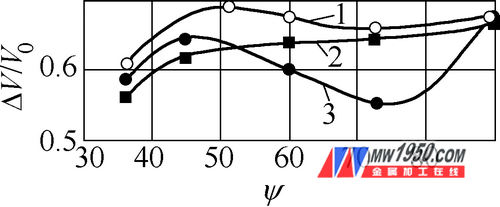
1-opening angle 128.6°2-opening angle 108°3-opening angle 90°
When the length is up, the flip angle is 51.4°, the opening angle of the lower anvil is 128.6° forging into a octahedron; the flip angle is 72°, the opening angle of the lower anvil is 108°, and the pentahedron is forged to ensure better pore closure index (see figure 2 Curves 1, 2), the specified polyhedral shape is maintained under these two forging process conditions. The worst result under all conditions is the flip angle
<36°, and the optimum flip angle is 90°. Then, the blank section conditions are close to square, which improves the closure condition of the pores.
In order to improve the forgeability of metals on composite anvils, many forging methods have been proposed. All of these methods are characterized by a large amount of blank deformation, that is, a large reduction in the initial stage of forging, first turning 180° to obtain a near slab shape, and then turning 90° to obtain a nearly square shape. Figure 3 shows one of the cases of using this forging method.
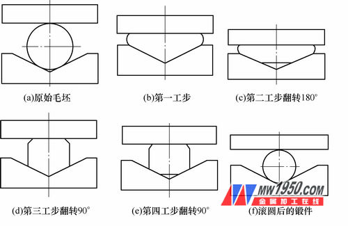
Figure 3: The forging process after the lengthening of the combined anvil
Figure 3 is close to the "plate-square" section, which has the advantage that the forging in the diamond anvil according to option 2 has a small reduction and flip angle, on the anvil at the large opening (> 105 °), when the section When the shape is compressed to near a circle, horizontal tensile stress occurs, which will deteriorate the axial region of the forging and prevent its internal pores from closing. When the large reduction of the contact area between the blank and the anvil working surface is increased, the frictional force acting as a support is increased, resulting in the occurrence of compressive stress in the axial region of the blank, thereby improving the closing condition of the pore. If the polygon is contacted at an angle according to the prescribed polygon, the contact area can also be increased. For round forgings, the octagon (top angle 135°) theoretically meets this condition and is compressed by 90°, then 45°, 22.5° on a diamond anvil with an opening of 135°. The conclusions for the study of the octagonal cross section and the unclosed pore model indicate that on the above anvil, the first compression can be better closed. Sampling and analysis by axial drilling, the axial aperture of the forgings obtained by this route is closed faster than other forging schemes.
The study of the center deformation of the 90°, 105°, 120° and 135° diamond anvils by the slip line method indicates that the maximum depth of the plastic deformation along the cross section is 135° in the opening angle of the anvil.
In the case 2 with the open angle anvil, the corresponding blank radius RP and the anvil opening radius RZ are as shown.

Figure 4 Round billet forging scheme in anvil with an open angle
From the viewpoint of the elongation factor and the production efficiency, when RP = RZ (see Fig. 4b), the blank is wrapped at an angle of 60 to 75. Under this condition, the deformation center is subjected to high compressive stress. However, this ideal condition is difficult to achieve in practice, because in practice, the anvil is often replaced by RP<RZ.
In the case of forging large forgings, in order to avoid the frequently changing anvil, the opening angle of the anvil is much smaller than the blank angle of the blank, and the relationship is RP/RZ=2. Because the stress state is close to the round forging on the flat anvil, there is a very large tensile stress in the axial region of the forging, and the solution RP<RZ (see Figure 4c) cannot be adopted. A small amount of reduction under this condition can cause axial looseness. Experience has shown that, according to options 1 and 2, in combination anvils, especially in diamond-shaped anvils, as the cross-sectional dimensions of the forgings decrease, the porosity also decreases, which is the best solution for improving the service life of the parts.
Several other pore closure mechanisms are plate-shaped or square-shaped on the flat anvil (Scheme 3). At large reductions, the pores transform into cracks and are forged when there are favorable conditions. Whether these cracks can be all welded together with high temperature and high compressive stress is conditioned by the large frictional force of the force and reaction, and even the large axial deformation.
Many years of practical experience in the manufacture of shaft-rolled forgings have shown that satisfactory results can usually be obtained after plate-shaped or square forging. The forgings are ultrasonically tested and the internal pores are completely forged. After obtaining the shape of the plate or square, the octagonal shape must be forged on the flat anvil according to this scheme, and then rounded on the combined anvil or diamond anvil. Some defects are created in the solution studied because the axial region creates tensile stress when forging the octagonal section. If tested with lead, the junction of the cross section, the diameter of the circular section is exactly half the diameter of the blank. The desired shape is obtained by a plate-shaped or square-forged circular shape or even a completely round blank shape, as shown in FIG. In this case, it is possible to obtain some anisotropy in which the shaft member is forged only by the slab.
(a) Forgings equal to 1/2 diameter of blank (b) y=2.3 after slab forging (c) Lead forgings after forging y=3.3
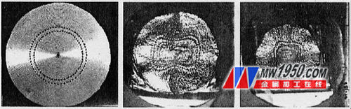
Fig. 5 Change in diameter shape of lead sample after forging
Forging on the flat anvil according to option 4 can ensure high-quality forgings. Under the condition of obtaining square-section forgings, the requirements can only be met when the process is limited. If a circular section is forged on a flat anvil, looseness is inevitably generated in the axial direction.
For more information, please see the contents of the first issue of Metalworking (Hot Processing) 2013.
Geosynthetic Clay Liner,Bentonite Clay Liner,Geosynthetic Clay Liner
Silane Coupling Agent Co., Ltd. , http://www.nsgeosynthetics.com